XPort Leaf Kit: Assemble
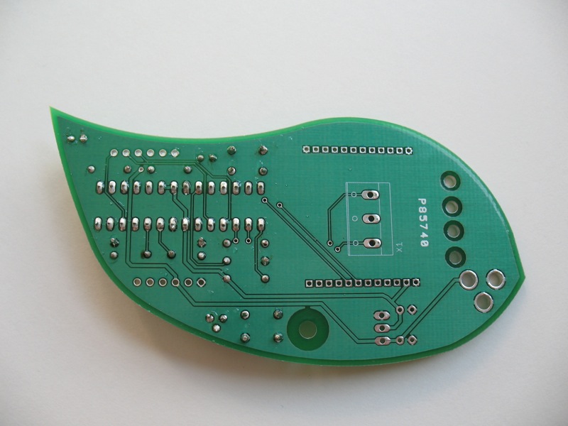
1. The Leaf Board
Now you can start assembling your board.


Turn on your soldering iron and give it some time to heat up. Reference your soldering iron manual if you’re not sure what temperature to set it to.
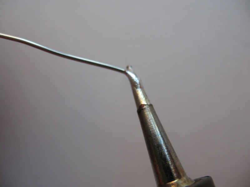
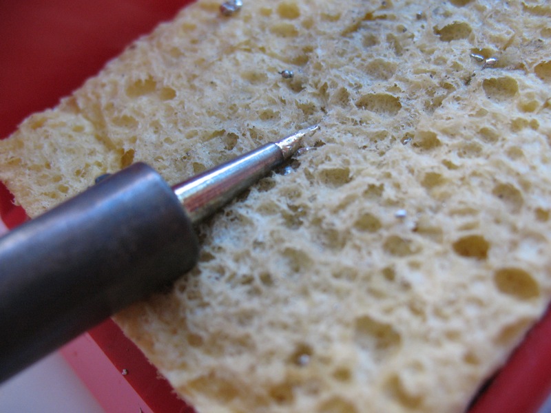
Once your iron is heated up, tin the tip by pressing solder into the tip, then wipe away the excess on a damp sponge. Here’s an excellent video tutorial on soldering we found online.

Now you’re ready to begin.
2. Resistors
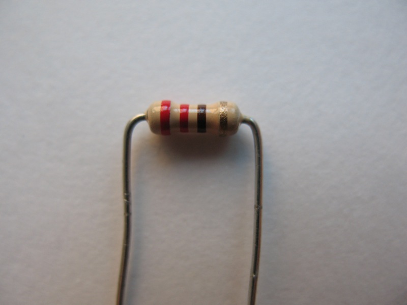
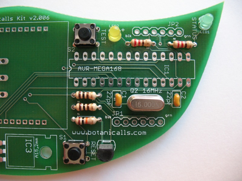
First we’ll start with the resistors. Take the 220 ohm resistor – it’s identified by the color bands “red, red, brown, gold”. Take your needle nose pliers and bend the legs of the resistor 90 degrees each so they’re pointed in the same direction.
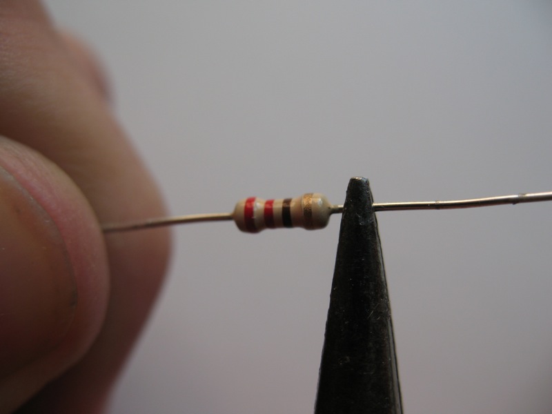
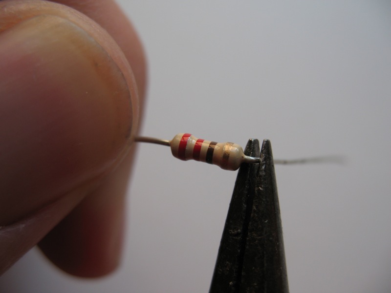
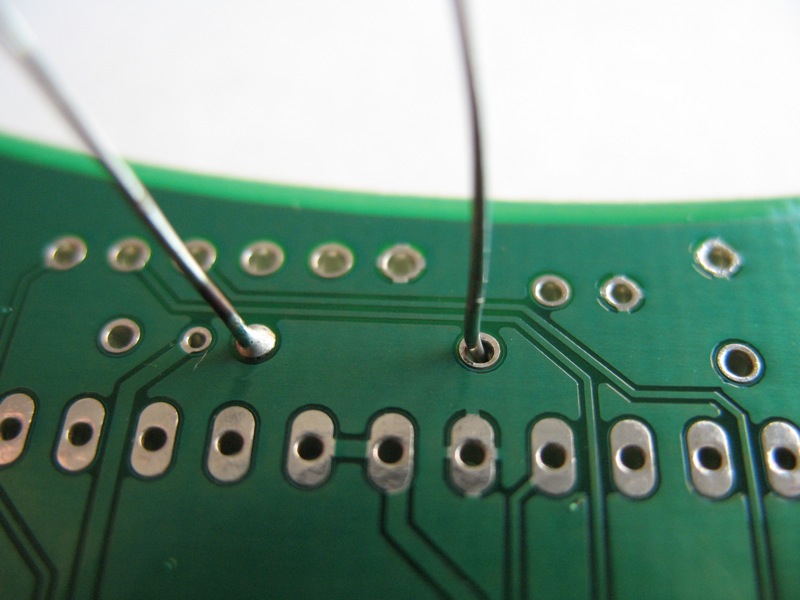
Find marking for the 220 resistor on the leaf. Slide the legs through the holes. Once the resistor is place, you can bend the legs out slightly to hold it in place when you turn the board upside down.


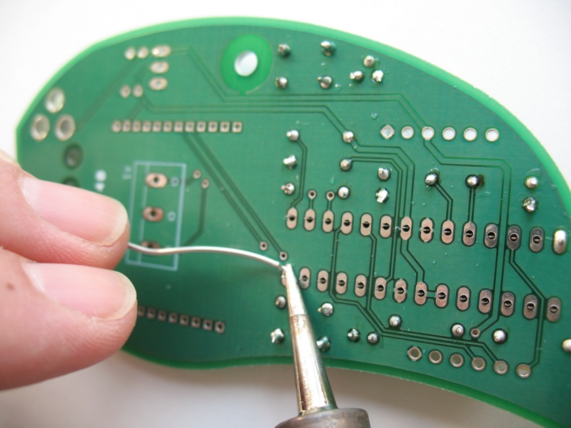
Place the tip of your soldering iron at the joint where the resistor leg and the edge of the hole meet. Press the solder into this junction so it melts and flows freely. Once the junction is covered, remove the iron and solder.


Repeat for the other leg. Once both legs are soldered, take your small snips and snip the resistor leg just above the solder.


Repeat this process with the other 220 ohm resistor, as well as the 100 ohm (brown, black, brown, gold) and 10K resistors (brown, black, orange, gold).

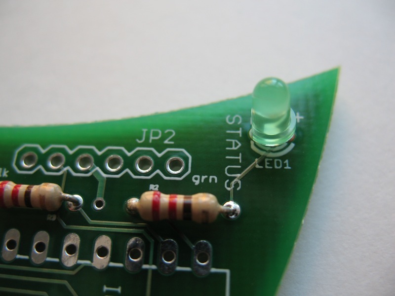
3. LEDs
FInd your LEDs (light-emitting diodes). LEDs are polarized, which means there’s a positive and and a negative leg, so it’s important to make sure that the correct leg goes into the correct hole. You can tell identify the positive side because that leg is longer.
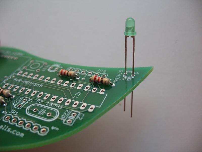
There are two LEDs for your leaf board. One, labelled “status”, will light to give you information about the moisture level of your plant’s soil. The other, labelled “test”, will light to indicate various communication activity.
Take the green LED and insert it into the “Status” light location. Make sure that you put the longer positive leg into the hole marked “+” and the shorter negative leg in the hole marked “-”. Once the LED is inserted, flip the board. You can spread the legs on the LED, just as you did with resistors, to hold it in place.

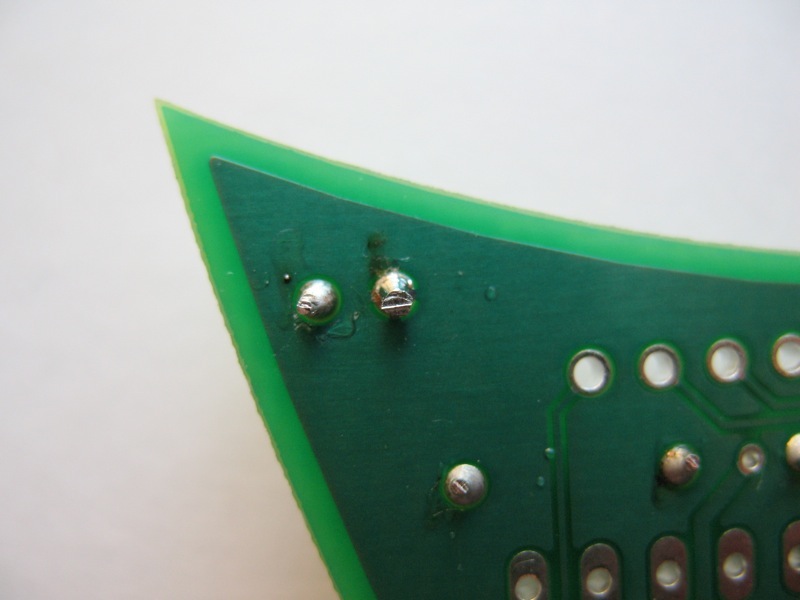
Solder and then snip the legs of the LED.
Place the yellow LED in the “test” slot the same way, longer leg into +, shorter leg into -, then solder and snip.

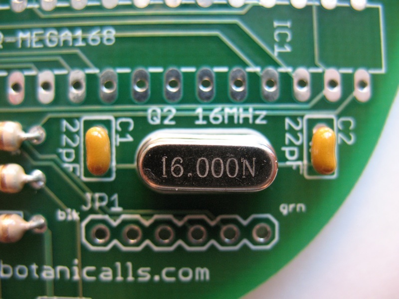
4. 16MHz crystal
Insert the crystal. There’s no polarity here so it can go in either way. Solder in place and snip the leads.

5. 22pF capacitors
These smaller capacitors are not polarized, so they can be inserted in either direction. Insert the capacitors, solder in place, and snip the excess leads.
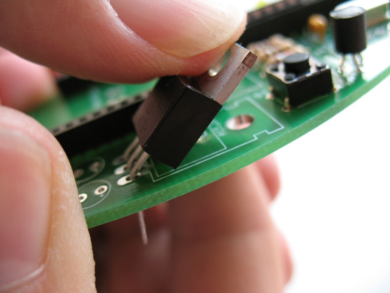
6. 2N2222A Transistor
Take the transistor. Gently bend the center lead out toward the rounded side.


Line up the transistor so the flat side matches the outline on the board.
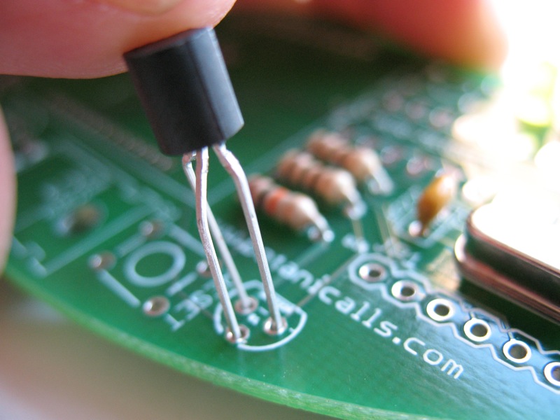

Insert the legs and pull through. It may help to use your needle nose pliers.

The transistor will sit approximately 1/4″ above the board (see photo above). Solder in place and snip the leads.

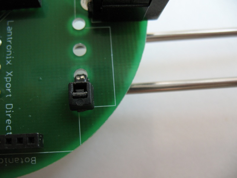
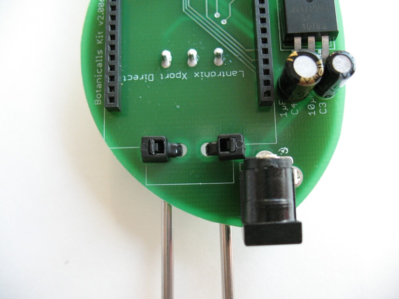
7. Switches
There are two tactiles switches. Only one alignment will fit. They will pop into the board when you press on them.


Solder them into place. You will not need to snip the legs because they are short already.


8. IC socket
Insert the IC socket, noting the notch on the end.
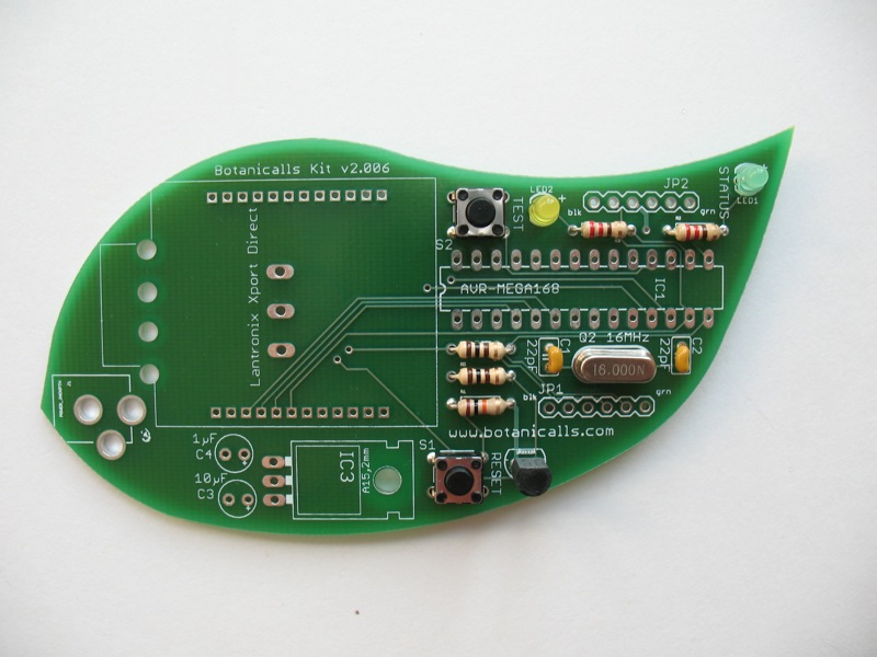

Make sure the notch of the socket lines up with the notch on the outline of the board.

Use a small piece of masking tape to secure the socket in place.

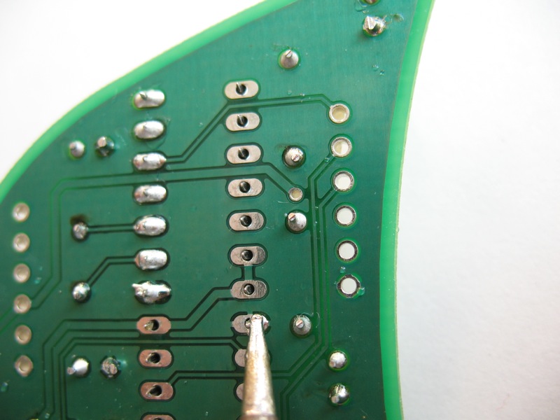
Flip the board. At first, solder only the two pins on opposing corners to secure the socket in place.

Check to make sure that the socket is seated flush on the board. If it’s not, reheat your solders and push the socket it. Once it’s positioned correctly, solder all of the remaining pins.
When you are finished, remove the tape.

9. XPort Headers
There are two sets of 12-pin 2mm female headers for the XPort. Insert them as show and use tape to hold them in place.


At first, solder just one pin on the end of each row.

Remove the tape and check to see that the headers are flush to board and at a straight 90 degree angle. If they are not straight, gently push them into alignment.

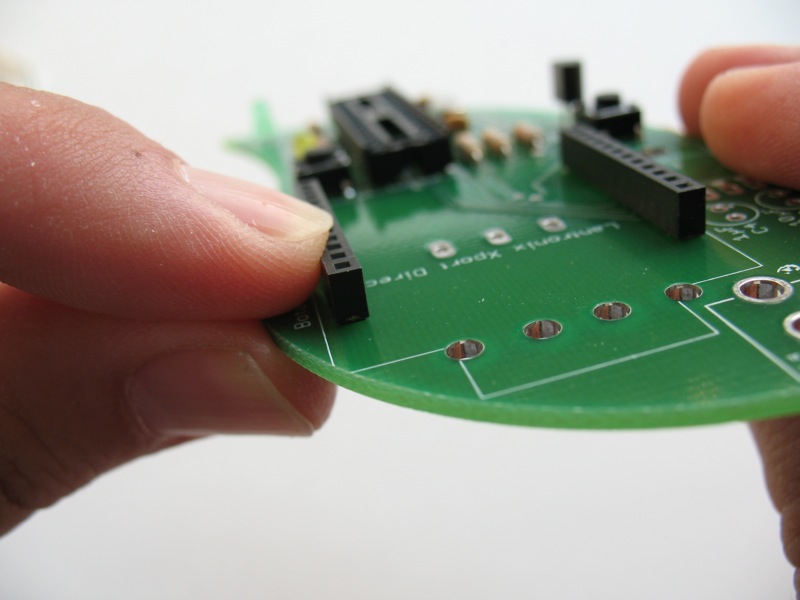
Solder the remaining pins.

Note: These pins are close together, so be careful not to use excess solder as it might cause the pins to touch.
10. Voltage regulator
Insert the voltage regulator as shown.

Gently bend it over so it lies flat against the board.


Slide it so the hole in the regulator lines up with the hole in the board.

Turn the board over and solder the pins in place. Snip the excess.


11. Male headers
There are two sets of male headers. Insert the short ends of the headers into the board.

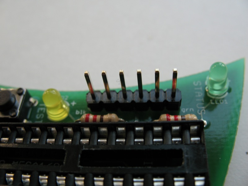
Tape the headers in place. Turn the board over and solder in place.

Straighten if necessary.

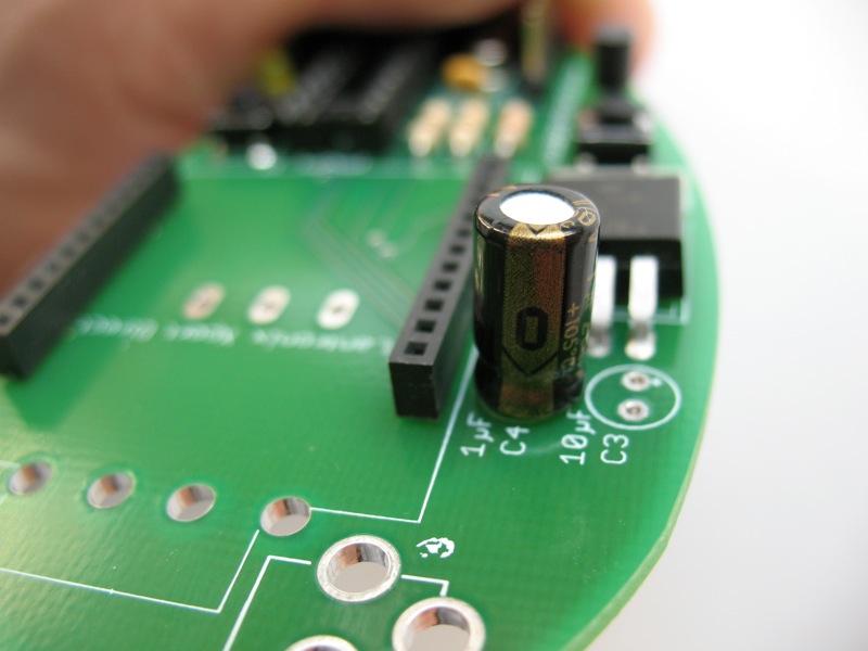
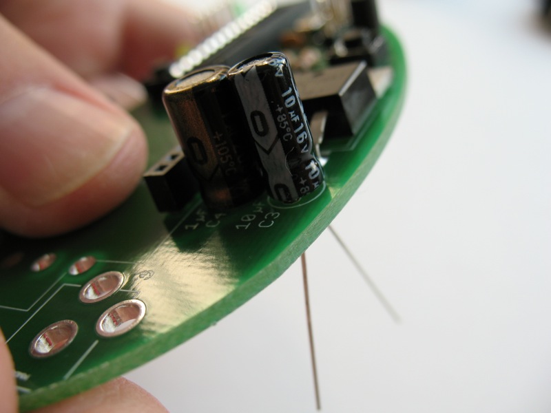
12. Electrolytic capacitors
Take your 10µF and 1µF capacitors. These capacitors are polarized, so it’s very important to pay attention to which holes you put them in. The longer leg should go through the hole marked with a “+” sign. The shorter leg, on the same side of the capacitor with the stripe, goes into the unmarked hole.

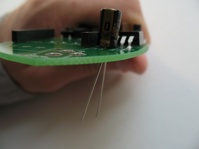
Put the capacitors in place, double-check you inserted them the right way, then spread the legs, solder and snip.
13. Power jack
Insert the power jack so the opening is facing the edge of the board. Carefully but firmly press the jack so it snaps into place. The back leg may take a bit of force, so don’t give up if it doesn’t slide in at first. Turn the board over and solder. Use enough solder so that the holes are completely filled.


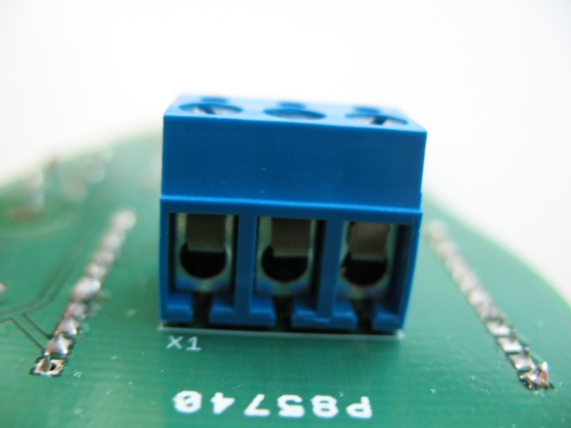
14. Terminal block
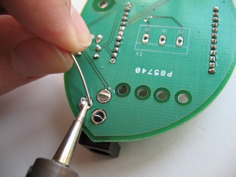
Turn the board over. The terminal block gets put in from the reverse side of the printed circuit board, as shown. On the back side of the board matching the outline, place the terminal block so the metal openings are facing the same direction as the opening of the power jack.

Tape in place. Turn the board so you are once again looking at the front. Solder the leads of the terminal block. Remove the tape.


15. AVR-MEGA168 microcontroller
Match the notch at one end of the microcontroller to the notch of the socket.
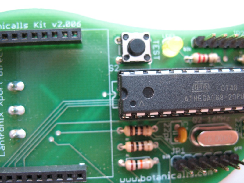
Gently press the chip all the way into place, taking care to not bend any of the legs.


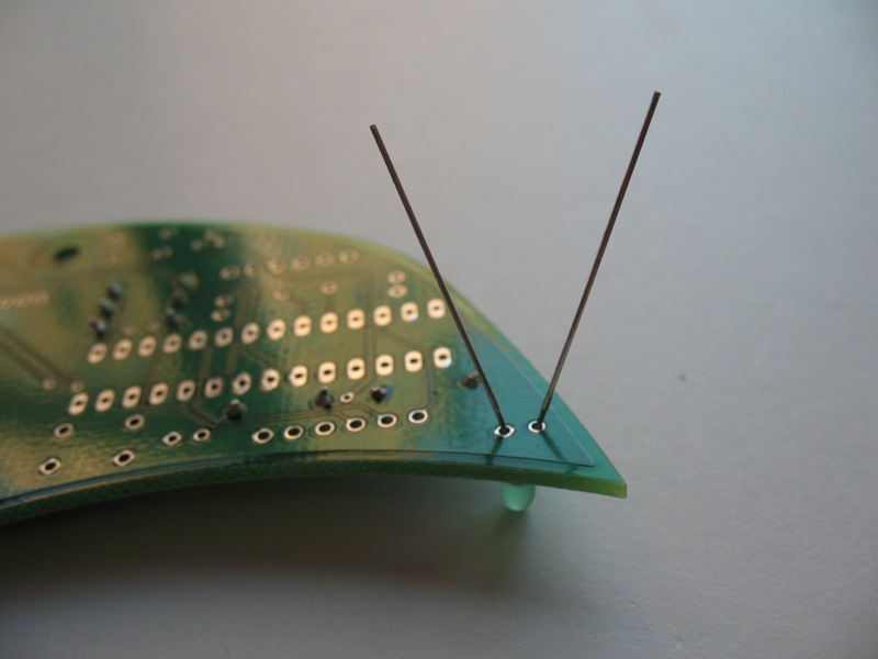
17. Moisture probes
Using a small, flathead screwdriver, unscrew the left and right screws of the terminal block so that the holes are completely open.

Insert the steel moisture probes all the way into these holes.
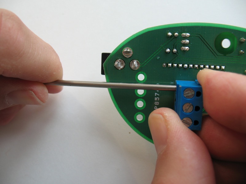
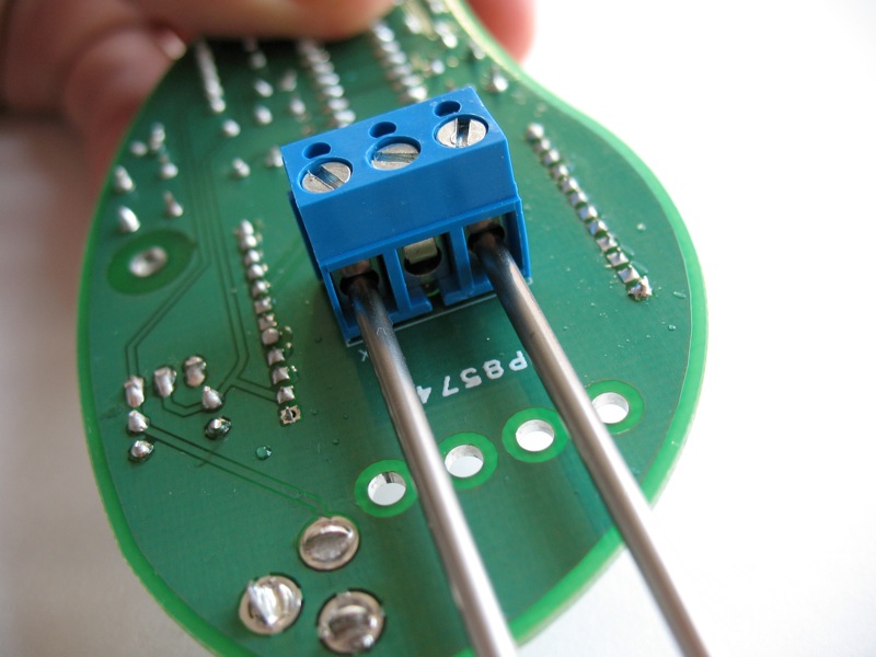
Screw closed the openings to securely hold probes in place.

18. Cable ties
To secure the probes in place, insert the two cable ties through the holes so they loop around the probes as pictured.
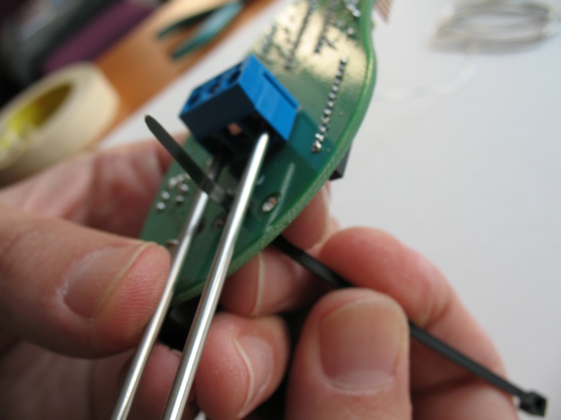
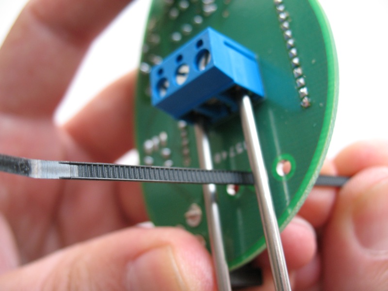
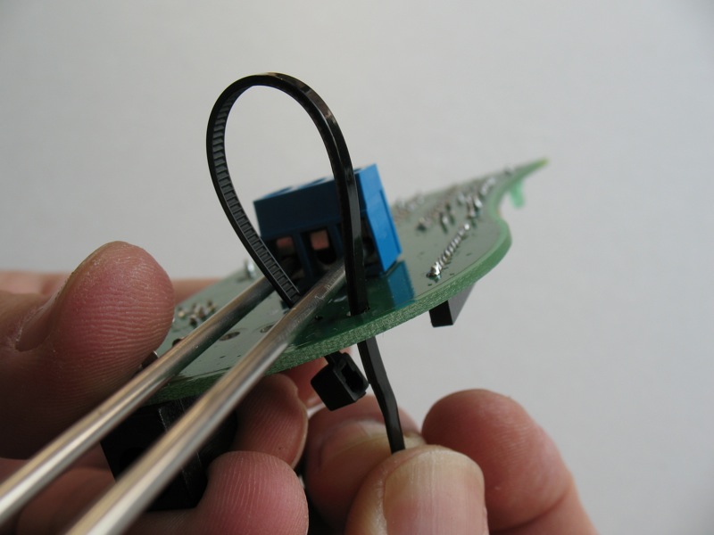
Pull the tab tightly so that probes are pulled close to the board.
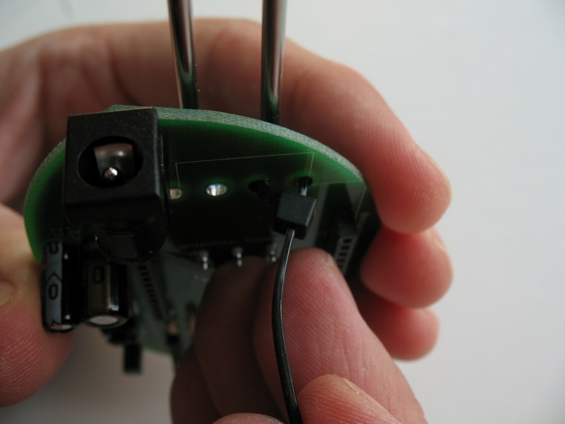
One the ties are secure, snip the excess length.


19. XPort
Insert the XPort carefully into the female headers with the port facing the edge of the board.


New kits are here!

Categories
- Announcements (8)
- Press (5)
Pothos Plant Tweets
Flickr Feed
Meta

This work is licensed under a Creative Commons Attribution-Noncommercial-Share Alike 3.0 United States License.