|
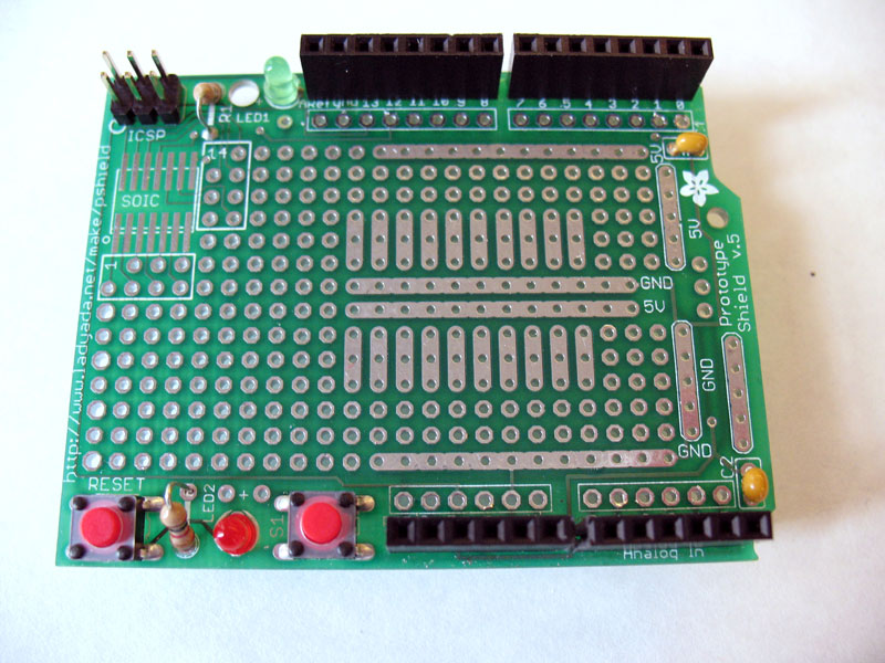
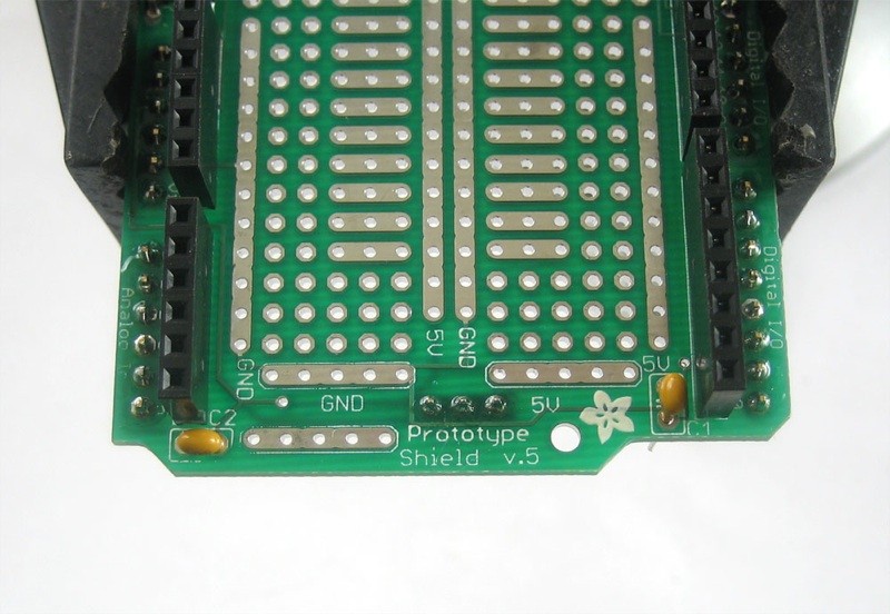
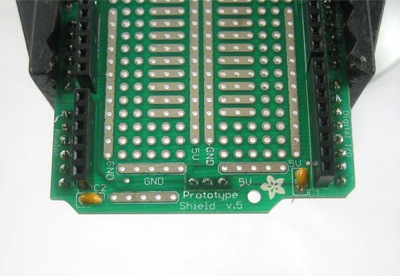
Instructions for soldering the basic Proto Shield are available on LadyAda.net. You'll be following these up to a point. Stop after soldering in the resistors. Do NOT place the 4 short 8-pin and 6-pin female headers That are included in the protoboard kit. Do NOT place the male headers.
Place one of the longer 8 pin Shield Stacking headers in the outer row of digital pin holes marked 0 through 7. The other will go in the outer row of digital pin holes marked 8 through AREF. Solder both in place from the bottom of the Proto Shield board. DO NOT TRIM THE LONG METAL LEADS, YOU WILL NEED THEM TO STACK THE SHIELDS. |

|
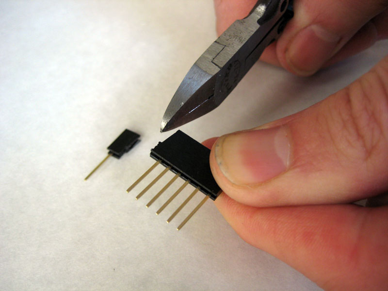
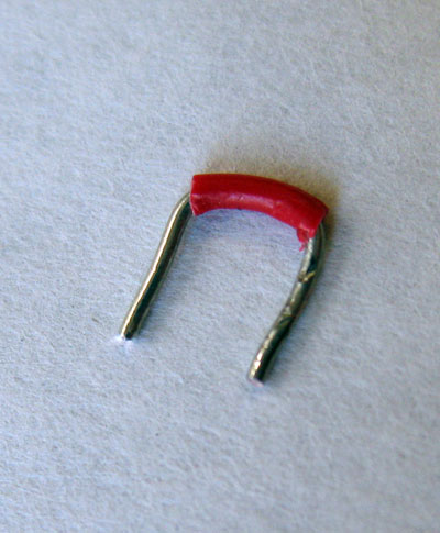
Use your snips to cut two pins off the two other of the longer 8 pin Shield Stacking headers. You should end up with a roughly trimmed 6 pin Shield Stacking header. Snip in the middle of the second pin as shown. |
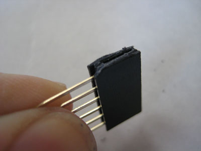 |
Rough ends are okay! Don't trim too close. |
 |
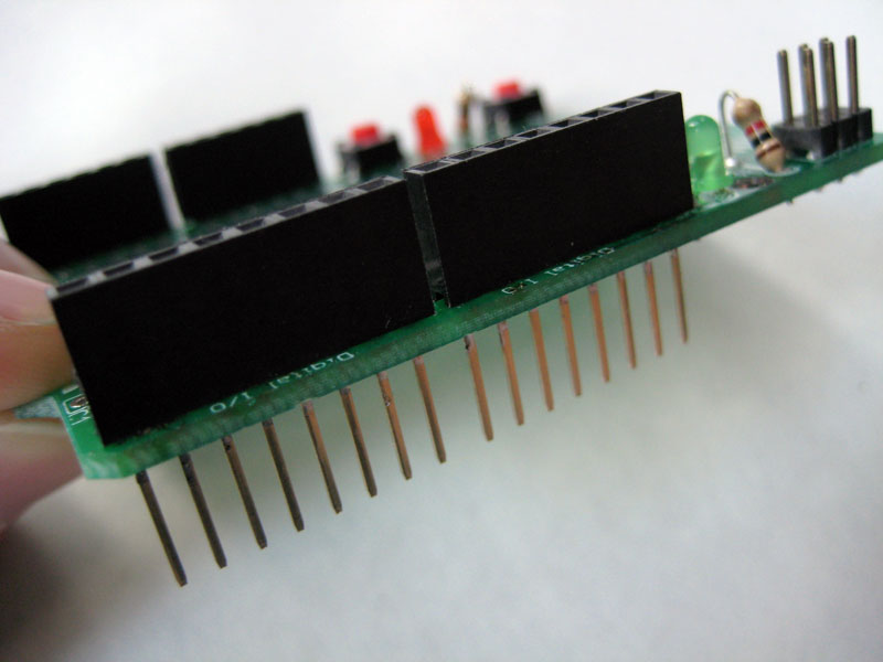
Place one of the newly cut 6 pin Shield Stacking headers in the outer row of analog pin holes marked 0 through 5. The other will go in the outer row of pin holes marked RST through Vin. Solder both in place from the bottom of the Proto Shield board. DO NOT TRIM THE LONG METAL LEADS, YOU WILL NEED THEM TO STACK THE SHIELDS. |
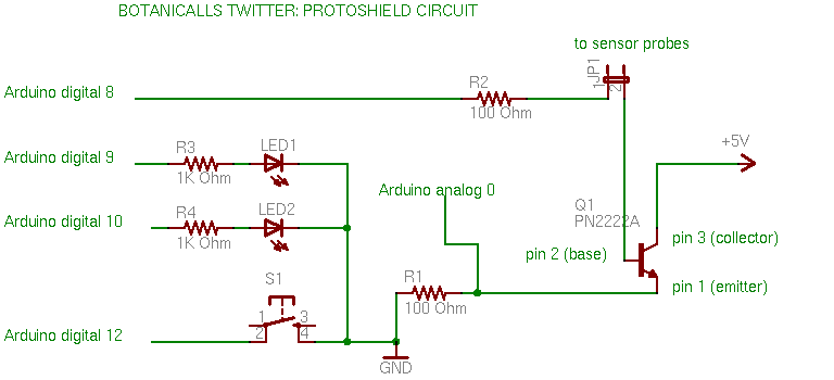 |
Here's a schematic of the circuit you'll be building on the protoboard in the next steps. Click on it to see it full size. |
|
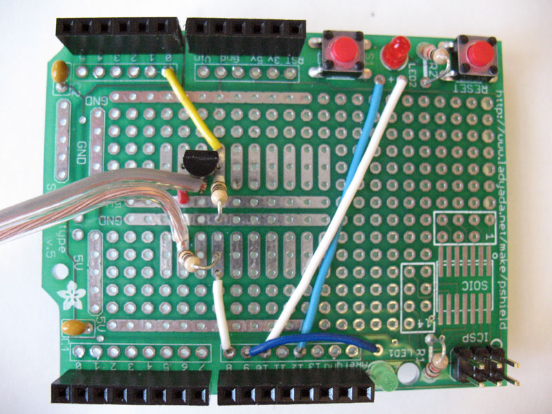
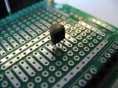
Place the transistor as shown in the photo with the flat side facing the analog pins. |
 |
Turn the board over and bend the lead wires slightly, so that it doesn't fall out while you are soldering it in. |
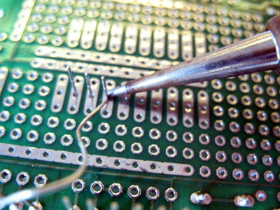 |
When soldering, tin your iron with a bit of solder and make sure you heat both the metal lead and the metal pad well so that solder melts and flows easily across both. |
 |
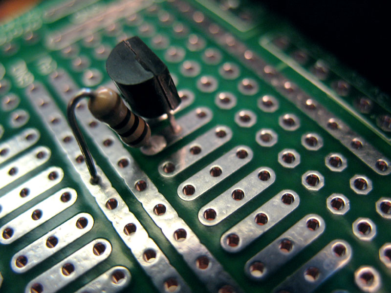
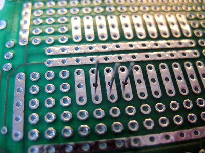
Once it's soldered in properly, clip the leads as shown, close to the board. All the other components can be attached in the same manner. |
 |
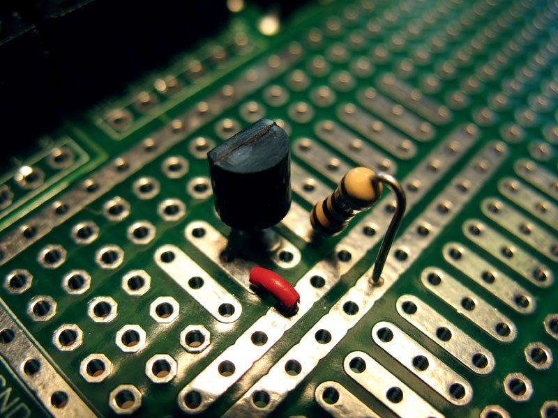
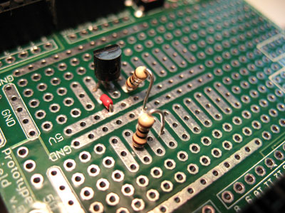
Next, place one of the 100 Ohm resistor as shown, with one leg in the same three-hole bus (silver metal that joins holes together) as the transistor's emitter pin. The other leg of the resistor goes into the ground bus. Resistors are bipolar, so it doesn't matter which way it faces. Solder it in place and trim the leads. |
|
Cut a short length of wire and use it to connect the collector pin of the resistor to the 5 Volt bus as shown. You'll need to strip the insulation off both ends of the wire. We left some insulation on the middle of the wire in our photo, but for this connection it's not necessary so you could also just use bare wire. |
 |
Solder it in place and trim the excess wire. |
 |
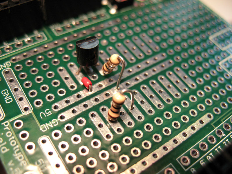
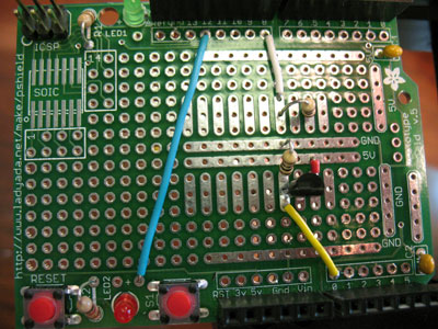
Place the other 100 Ohm resistor so that it forms a connection between two different three-hole busses on the other side of the proto board from the transistor, as shown in the photo. Solder it in place and trim the leads. |
 |
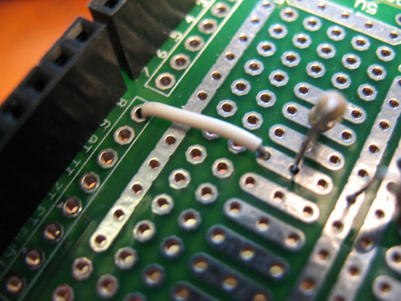
Cut a short length of wire, strip the ends and use it to connect from the same three-hole bus as one leg of the resistor you just placed to Arduino digital pin 8. It's important to have insulation on this wire, and on all the ones that follow so that it doesn't accidentally touch something else on the board and create a short-circuit. Solder it in place and trim the excess wire. |
 |
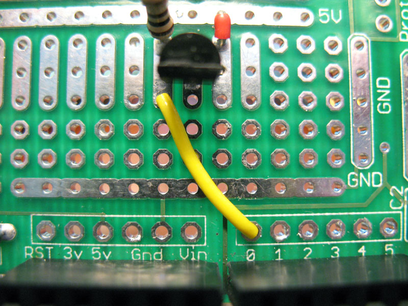
Cut a short length of wire, strip the ends and use it to connect from the same three-hole bus as the emitter pin of the resistor to Arduino analog pin 0 (zero). Solder it in place and trim the excess wire. |
 |
Use wire to connect Ardunio digital pin 12, to the + connection for the switch (S1). Solder and trim as before. |
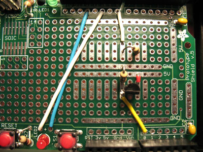 |
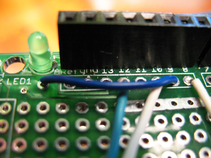
Use wire to connect Arduino digital pin 10 to the LED 2 connection. Solder and trim. |
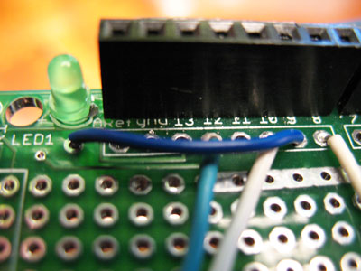 |
Use wire to connect Arduino digital pin 9 to the LED 1 connection. Solder and trim. |
 |
Solder the two ceramic capacitors into the holes for C1 and C2. Ceramic capacitors are bipolar so their orientation doesn't matter. |

|
Separate the two ends of the speaker wire opposite from where you soldered the nails. Strip a short amount off the end of each conductor. Twist those together and lightly tin the ends with solder, just enough to join the strands. One wire should be inserted into the same three-hole bus as the transistor's center base pin. The other wire should be inserted into the three-hole bus with the 100 Ohm resistor that connects to Arduino digital pin 8. Solder them both in place carefully and trim the leads.
You're now done with the Proto Shield and ready to put it all together! |